Vehicle Architecture and System Design
Chapter 04 · Automotive Product Development
Use the infographic for the process overview, then follow the chapter sections for definitions, activities, deliverables, gate evidence, and implementation detail.
Chapter infographic
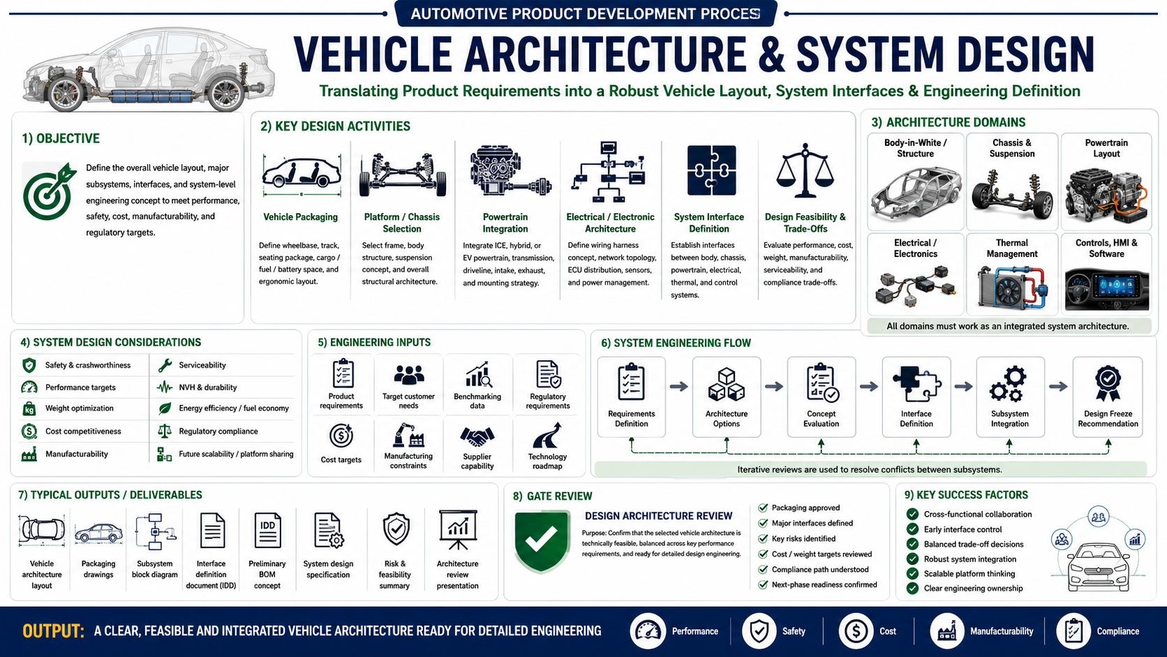
Vehicle Architecture & System Design in Automotive Product Development
Translating Product Requirements into a Robust Vehicle Layout, System Interfaces & Engineering Definition
Vehicle Architecture and System Design is one of the most important stages in the Automotive Product Development Process. It converts customer requirements, product targets, regulatory needs, and business objectives into a complete vehicle-level engineering concept.
At this stage, the team defines the overall vehicle layout, major subsystems, system interfaces, packaging strategy, platform selection, powertrain integration, electrical and electronic architecture, and feasibility of the complete product.
A strong vehicle architecture ensures that the product is technically feasible, manufacturable, serviceable, cost-effective, compliant, and scalable for future variants.
Safety-related E/E architecture must allocate monitoring, independence, fault response, interfaces, and safe-state behaviour early enough to influence the system design. See Functional Safety (FuSa) in Automotive for the ISO 26262 lifecycle, HARA, FSC, TSC, and safety-mechanism context.
1. Objective of Vehicle Architecture & System Design
The main objective is to define the overall vehicle layout, major subsystems, interfaces, and system-level engineering concept to meet:
- Performance targets
- Safety requirements
- Cost targets
- Manufacturability
- Serviceability
- Regulatory compliance
- Customer expectations
- Future platform scalability
In simple words, this phase answers the question:
“How will the complete vehicle be physically, functionally, and technically arranged before detailed design starts?”
For example, in a passenger car, this includes wheelbase, track width, seating layout, engine or battery location, chassis structure, suspension concept, cooling layout, wiring architecture, electronic control units, and major system interfaces.
For a motorcycle, this includes frame layout, engine mounting, fuel tank location, rider triangle, suspension geometry, exhaust routing, electrical harness layout, braking system layout, cooling system, and service access.
2. Key Design Activities
2.1 Vehicle Packaging
Vehicle packaging defines how major components and occupants are arranged within the available vehicle space.
It includes:
- Wheelbase
- Track width
- Seating position
- Cargo space
- Engine space
- Battery space
- Fuel tank location
- Suspension travel
- Ground clearance
- Ergonomic layout
- Service accessibility
Good packaging ensures that the product provides the required comfort, usability, performance, and serviceability without creating conflicts between systems.
For example, increasing battery capacity in an EV may improve driving range, but it can also affect ground clearance, vehicle weight, cost, and crash safety. Therefore, packaging decisions must be balanced carefully.
2.2 Platform / Chassis Selection
The platform or chassis is the foundation of the vehicle.
This activity includes selection of:
- Vehicle platform
- Frame type
- Body structure
- Chassis concept
- Suspension layout
- Mounting strategy
- Structural architecture
Typical options include:
- Existing platform
- Modified platform
- New platform
- Modular platform
- Shared global platform
For passenger cars, platform decisions affect body structure, crash performance, manufacturing investment, and model flexibility.
For motorcycles, chassis selection affects handling, weight, stiffness, comfort, cost, and performance.
2.3 Powertrain Integration
Powertrain integration defines how the engine, motor, transmission, driveline, exhaust, intake, cooling, and mounting systems are arranged in the vehicle.
For ICE vehicles, it includes:
- Engine location
- Transmission layout
- Intake system
- Exhaust system
- Fuel system
- Cooling system
- Mounting points
- Emission control system
For EVs, it includes:
- Battery pack location
- Motor layout
- Inverter placement
- Charger location
- High-voltage cable routing
- Thermal management
- Battery protection strategy
Powertrain integration must balance performance, NVH, cooling, serviceability, crash safety, and regulatory requirements.
2.4 Electrical / Electronic Architecture
Modern vehicles depend heavily on electrical and electronic systems. Therefore, E/E architecture is now a core part of vehicle architecture.
It includes:
- Wiring harness concept
- ECU distribution
- Sensor locations
- Actuator locations
- Network topology
- CAN/LIN/Ethernet communication
- Power distribution
- Fuse and relay locations
- Diagnostics strategy
- Software and control interfaces
For advanced vehicles, this may also include:
- ADAS sensors
- Camera systems
- Radar systems
- Connectivity modules
- Telematics
- OTA update capability
- Cybersecurity planning
A poor E/E architecture can create major issues during development, validation, homologation, and after-sales service.
2.5 System Interface Definition
System interface definition is one of the most critical activities in this phase.
It defines how different systems interact with each other, such as:
- Body to chassis
- Engine to frame
- Suspension to body
- Battery to vehicle structure
- Cooling system to powertrain
- Brake system to electronic control unit
- Wiring harness to electrical components
- Software to hardware
- Exhaust system to frame and body
- Fuel system to engine and control units
Interface problems are a common cause of development delays. For example, exhaust routing may conflict with rear suspension travel, or wiring harness routing may interfere with heat zones or service access.
To avoid such issues, interface control must start early.
2.6 Design Feasibility & Trade-Offs
Every architecture decision involves trade-offs.
Common trade-offs include:
The role of system design is to find the best balance between cost, performance, quality, safety, compliance, and customer value.
3. Architecture Domains
Vehicle architecture is not limited to one department. It includes multiple engineering domains that must work together as one integrated system.
3.1 Body-in-White / Structure
This domain covers the main structural body or frame of the vehicle.
It includes:
- Body structure
- Frame layout
- Crash load paths
- Mounting points
- Structural stiffness
- Weight optimization
- Corrosion protection
- Manufacturing feasibility
For motorcycles, this may include frame, sub-frame, swingarm mounting, engine mounting, and structural brackets.
3.2 Chassis & Suspension
This domain defines ride, handling, braking, steering, and road load capability.
It includes:
- Front suspension
- Rear suspension
- Steering geometry
- Brake system layout
- Wheel and tyre package
- Ground clearance
- Ride comfort
- Handling balance
Suspension layout must be integrated with body structure, wheel movement, brake hose routing, ABS sensors, and packaging space.
3.3 Powertrain Layout
This includes the physical and functional integration of the vehicle propulsion system.
It covers:
- ICE engine
- Hybrid system
- EV motor
- Transmission
- Battery pack
- Driveline
- Intake system
- Exhaust system
- Cooling system
Powertrain layout strongly influences vehicle performance, emissions, NVH, serviceability, and homologation readiness.
3.4 Electrical / Electronics
This domain manages all electrical and electronic systems.
It includes:
- Battery system
- Wiring harness
- ECUs
- Sensors
- Actuators
- Lighting
- Instrument cluster
- Diagnostics
- Communication networks
With increasing electrification and software content, E/E architecture has become one of the most complex areas of modern vehicle development.
3.5 Thermal Management
Thermal management ensures that all systems operate within safe temperature limits.
It includes cooling for:
- Engine
- Radiator
- Battery pack
- Motor
- Inverter
- Charger
- Cabin HVAC
- Brakes
- Electronics
Thermal design is especially important for EVs, hybrid vehicles, performance motorcycles, and high-load commercial vehicles.
3.6 Controls, HMI & Software
This domain covers the interaction between driver, vehicle controls, display systems, and embedded software.
It includes:
- Instrument cluster
- Infotainment
- Warning lamps
- Ride modes
- Drive modes
- ADAS functions
- Diagnostics
- Control logic
- Software calibration
- User interface
Controls and software must be aligned with safety, usability, regulatory, and customer experience requirements.
4. System Design Considerations
During vehicle architecture development, several engineering considerations must be reviewed.
Safety & Crashworthiness
The architecture must support occupant safety, pedestrian safety, crash load management, braking safety, lighting visibility, and regulatory safety requirements.
Performance Targets
Vehicle layout must support required acceleration, top speed, gradeability, handling, braking, range, fuel economy, and towing or load capacity.
Weight Optimization
Weight affects performance, fuel economy, EV range, braking, handling, emissions, and cost. Therefore, every system must be designed with weight targets.
Cost Competitiveness
Architecture should meet target cost while still delivering required customer value and regulatory compliance.
Manufacturability
The design must be practical for production. Manufacturing feasibility includes tooling, assembly sequence, welding, painting, automation, quality control, and process capability.
Serviceability
The vehicle must be easy to inspect, repair, maintain, and diagnose. Poor serviceability increases warranty cost and customer dissatisfaction.
NVH & Durability
The architecture must control vibration, harshness, noise, fatigue, and long-term durability.
Energy Efficiency / Fuel Economy
For ICE vehicles, architecture affects fuel economy through weight, aerodynamics, rolling resistance, and powertrain efficiency.
For EVs, it affects battery range, thermal efficiency, motor efficiency, and energy recovery.
Regulatory Compliance
The architecture must support compliance with applicable safety, emission, lighting, braking, EMC, noise, OBD, battery, and homologation regulations.
Future Scalability / Platform Sharing
A good architecture allows future variants, different body styles, multiple powertrains, regional adaptations, and model upgrades with minimum redesign.
5. Engineering Inputs Required
Vehicle Architecture and System Design require multiple inputs from different teams.
Product Requirements
These define what the vehicle must achieve in terms of performance, features, quality, cost, timing, and customer expectations.
Target Customer Needs
Customer expectations influence comfort, styling, features, performance, safety, usability, and ownership cost.
Benchmarking Data
Competitor vehicle data helps define target values for dimensions, performance, cost, features, quality, and customer appeal.
Regulatory Requirements
Regulations define mandatory design boundaries. These may include emission, safety, braking, lighting, noise, EMC, OBD, battery safety, and type approval requirements.
Cost Targets
Architecture must be designed within approved cost targets, including material cost, tooling cost, manufacturing cost, and warranty cost.
Manufacturing Constraints
The design must be compatible with plant capability, assembly process, available machinery, tooling investment, and production volume.
Supplier Capability
Supplier readiness influences technology selection, component feasibility, development timing, quality, cost, and localization.
Technology Roadmap
Future technologies such as EV platforms, ADAS, connected systems, lightweight materials, and software-defined vehicle architecture must be considered during system planning.
6. System Engineering Flow
The system engineering flow provides a structured method to convert requirements into a feasible vehicle architecture.
Step 1: Requirements Definition
The team defines vehicle-level and system-level requirements.
Examples
- Vehicle dimensions
- Performance targets
- Safety targets
- Cost targets
- Regulatory targets
- Fuel economy or range target
- Weight target
- Manufacturing requirements
- Step 2: Architecture Options
Multiple architecture options are created and compared.
Examples
- Existing platform vs new platform
- ICE vs hybrid vs EV
- Front-wheel drive vs rear-wheel drive
- Steel frame vs aluminium frame
- Air cooling vs liquid cooling
- Centralized ECU vs distributed ECU
- Step 3: Concept Evaluation
Each architecture option is evaluated based on technical, commercial, and regulatory criteria.
Typical criteria include:
- Customer fit
- Technical feasibility
- Cost
- Weight
- Performance
- Manufacturing feasibility
- Supplier availability
- Compliance feasibility
- Future scalability
- Step 4: Interface Definition
Major interfaces are defined and controlled.
Examples
- Engine mounting interface
- Battery mounting interface
- Suspension mounting interface
- Harness connector interface
- Cooling hose interface
- Brake control interface
- Software communication interface
Interface Definition Documents are created to avoid conflicts during detailed design.
Step 5: Subsystem Integration
Subsystems are integrated into the complete vehicle architecture.
This includes:
- Mechanical integration
- Electrical integration
- Thermal integration
- Software integration
- Manufacturing integration
- Service integration
- Step 6: Design Freeze Recommendation
After architecture review and feasibility confirmation, the team recommends the selected architecture for detailed engineering.
The output is a clear, feasible, and integrated vehicle architecture ready for the next development phase.
7. Typical Outputs / Deliverables
At the end of this phase, the following deliverables are normally prepared.
Vehicle Architecture Layout
A complete layout showing major vehicle dimensions, system locations, and package boundaries.
Packaging Drawings
Drawings showing placement of passengers, engine, battery, suspension, wheels, fuel tank, cargo area, and other key systems.
Subsystem Block Diagram
A high-level diagram showing major systems and their relationships.
Interface Definition Document
A document defining system interfaces, mounting points, connection points, electrical interfaces, thermal interfaces, and software communication points.
Preliminary BOM Concept
A first-level Bill of Material concept showing major components and system structure.
System Design Specification
A document defining system requirements, design assumptions, performance targets, and integration requirements.
Risk & Feasibility Summary
A summary of technical risks, cost risks, regulatory risks, supplier risks, and mitigation plans.
Architecture Review Presentation
A management-level presentation summarizing architecture options, selected concept, trade-offs, risks, and readiness for detailed engineering.
8. Gate Review – Design Architecture Review
The Design Architecture Review is a formal checkpoint before entering detailed design.
Purpose
To confirm that the selected vehicle architecture is technically feasible, balanced across key performance requirements, and ready for detailed engineering.
- Review Criteria
The following points should be confirmed:
- Packaging approved
- Major interfaces defined
- Key risks identified
- Cost targets reviewed
- Weight targets reviewed
- Compliance path understood
- Manufacturing feasibility reviewed
- Serviceability reviewed
- Supplier capability checked
- Next-phase readiness confirmed
A successful gate review ensures that detailed design starts with a stable and agreed architecture.
9. Key Success Factors
Cross-Functional Collaboration
Architecture development requires strong coordination between product planning, design, R&D, manufacturing, quality, purchasing, suppliers, service, and homologation teams.
Early Interface Control
Most integration issues happen because interfaces are not clearly defined early. Interface control should start from the concept stage.
Balanced Trade-Off Decisions
Vehicle architecture must balance customer value, technical performance, cost, weight, safety, and compliance.
Robust System Integration
All domains must work together as one complete vehicle system. Mechanical, electrical, thermal, and software integration must be reviewed together.
Scalable Platform Thinking
A good platform should support future variants, powertrain options, regulatory updates, and regional market requirements.
Clear Engineering Ownership
Every system and interface must have a responsible owner. Lack of ownership leads to unresolved issues and development delays.
- Practical Example: Architecture Decisions for a New Motorcycle
For a new motorcycle, vehicle architecture may include the following decisions:
This shows how architecture decisions affect performance, cost, homologation, manufacturing, and customer experience.
- Practical Example: Architecture Decisions for an EV Passenger Car
For an EV passenger car, architecture may include:
EV architecture requires strong integration between mechanical, electrical, thermal, and software teams.
- Common Risks in Vehicle Architecture
Typical risks include:
- Packaging conflicts
- System interface mismatch
- Overweight design
- Cost target failure
- Poor service access
- Cooling performance issues
- NVH problems
- Supplier capability gaps
- Manufacturing process limitations
- Regulatory non-compliance
- Late design changes
- Electrical harness routing issues
- Battery protection concerns in EVs
- Insufficient future scalability
These risks should be identified and tracked from the architecture stage itself.
- Best Practices for Vehicle Architecture & System Design
Start with clear product requirements.
Use competitor benchmarking data.
Involve manufacturing, service, quality, and regulatory teams early.
Define system interfaces before detailed design.
Conduct packaging reviews using CAD.
Maintain interface control documents.
Use simulation and feasibility studies early.
Review cost and weight targets regularly.
Confirm homologation requirements before architecture freeze.
Plan for future variants and platform scalability.
Document assumptions, risks, and open points.
Conduct formal architecture gate reviews.
Conclusion
Vehicle Architecture and System Design is the foundation of detailed automotive engineering. It transforms customer needs, product strategy, business targets, and regulatory requirements into a practical and integrated vehicle concept.
A well-defined architecture improves product quality, reduces development risk, avoids late engineering changes, supports manufacturability, simplifies homologation, and ensures that the final vehicle meets customer expectations.
The final output of this phase is:
A clear, feasible, and integrated vehicle architecture ready for detailed engineering.
Key Takeaways
Vehicle architecture defines the overall layout and system structure of the vehicle.
It includes packaging, chassis, powertrain, electrical, thermal, software, and interface design.
Early interface control is essential to avoid integration issues.
Architecture decisions strongly affect cost, weight, performance, safety, serviceability, and regulatory compliance.
Cross-functional collaboration is the key to successful system design.
A strong architecture enables future variants, platform sharing, and long-term product competitiveness.
Reference tables from the source chapter
| Requirement | Possible Conflict |
|---|---|
| Low weight | Higher cost material |
| High performance | Higher fuel consumption |
| Large battery | Higher vehicle weight |
| More features | Higher electrical complexity |
| Better crash safety | Increased structural weight |
| Better comfort | Higher cost and packaging space |
| Lower cost | Reduced feature content |
| Better serviceability | More packaging space required |
Reference table 2
| Area | Architecture Decision |
|---|---|
| Frame | Trellis frame / perimeter frame / cradle frame |
| Engine | Single-cylinder / twin-cylinder / four-cylinder |
| Cooling | Air-cooled / liquid-cooled |
| Suspension | Telescopic fork / USD fork / monoshock |
| Brakes | Single disc / dual disc / ABS |
| Electronics | Basic ECU / ride-by-wire / traction control |
| Fuel System | Tank capacity, pump location, hose routing |
| Exhaust | Routing, catalyst location, silencer volume |
| Serviceability | Access to filter, spark plug, battery, ECU |
| Compliance | Emission, noise, lighting, braking, OBD |
Reference table 3
| Area | Architecture Decision |
|---|---|
| Battery | Underfloor battery pack |
| Motor | Front motor / rear motor / dual motor |
| Thermal | Liquid-cooled battery and motor |
| Platform | Dedicated EV skateboard platform |
| Charging | AC and DC charging architecture |
| Electronics | High-voltage and low-voltage architecture |
| Safety | Battery protection and crash load path |
| Software | BMS, VCU, diagnostics, OTA capability |
| Service | HV safety isolation and diagnostics |
| Compliance | Battery safety, EMC, functional safety |
Frequently asked questions
What does vehicle architecture define?
It defines the overall package, platform, major subsystems, electrical and electronic topology, interfaces, and system-level performance targets.
Why is interface definition critical?
A vehicle can fail even when individual subsystems work well if mechanical, electrical, thermal, software, or control interfaces are unclear or incompatible.
What is reviewed at architecture freeze?
Packaging, major interfaces, performance targets, risks, cost and weight status, compliance strategy, and readiness for detailed design are reviewed.