Advanced Driver Assistance Systems (ADAS): Sensors, Architecture, Functions, Validation & Safety
Engineering Deep Dives · AutoPDP
Sensors, perception, sensor fusion, driver-assistance functions, safety engineering, validation and intelligent mobility.
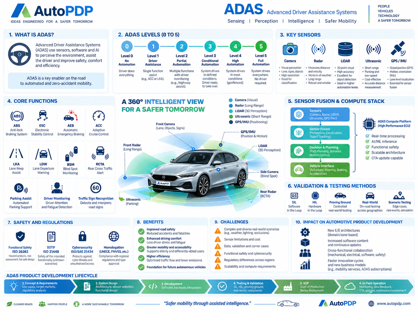
What this article covers
- Sensors, perception, fusion and driver-assistance functions
- Safety, human factors and scenario-based validation
- Regulatory scope, manufacturing calibration and field monitoring
Sensing, Perception, Intelligence and Safer Mobility
Advanced Driver Assistance Systems (ADAS) are electronic systems that use sensors, software, vehicle networks and computing platforms to perceive the driving environment, assist the driver and improve vehicle safety, comfort and efficiency.
The central ADAS engineering chain is:
Sense → Perceive → Fuse → Decide → Plan → Act → Monitor
ADAS may warn the driver, support a driving task, or—depending on the function and system design—control braking, steering or acceleration.
AutoPDP perspective: ADAS is a key technology path from conventional driver assistance toward increasingly automated, connected and software-defined mobility.
1. What Is ADAS?
ADAS combines data from multiple sensors and vehicle systems to detect, classify and track road users, lanes, traffic signs, obstacles and other environmental features.
A modern ADAS implementation typically includes:
- Cameras
- Radar
- LiDAR, where applicable
- Ultrasonic sensors
- GNSS/GPS
- IMU
- Vehicle-speed and chassis signals
- High-performance ADAS computing
- Sensor-fusion software
- Decision and planning software
- Vehicle-control interfaces
The system must perform in real time while meeting automotive requirements for reliability, safety, cybersecurity, diagnostics and validation.
2. Levels of Driving Automation
Driving automation is commonly described from Level 0 to Level 5. The precise responsibilities of the driver and automated-driving system depend on the supported operational design domain (ODD) and applicable definitions.
| Level | General Description | Typical Interpretation |
|---|---|---|
| Level 0 | No Driving Automation | Driver performs the dynamic driving task; warning/intervention systems may still exist |
| Level 1 | Driver Assistance | One driving-control dimension is assisted, such as longitudinal or lateral control |
| Level 2 | Partial Driving Automation | Longitudinal and lateral control can be automated together while the driver remains responsible for supervision |
| Level 3 | Conditional Driving Automation | Automated system performs the driving task within a defined ODD, with fallback-ready user requirements |
| Level 4 | High Driving Automation | Automated driving can operate without driver fallback within its defined ODD |
| Level 5 | Full Driving Automation | Driving automation across all conditions a human driver could manage |
ADAS functions such as AEB, ACC, LKA and BSM are often associated with Level 0–2 assistance, while higher automation requires significantly more sensing, computing, redundancy, safety engineering and validation.
3. Key ADAS Sensors
3.1 Camera
Cameras provide rich visual information for:
- Lane detection
- Traffic-sign recognition
- Object classification
- Pedestrian and cyclist detection
- Traffic-light recognition
- Surround-view functions
- Driver monitoring
Strengths: high semantic detail, color and object information.
Limitations: sensitivity to glare, darkness, fog, rain, dirt and occlusion.
3.2 Radar
Radar estimates object distance and relative velocity and is widely used for:
- Adaptive cruise control
- Forward-collision monitoring
- Automatic emergency braking
- Blind-spot monitoring
- Rear cross-traffic alert
Strengths: robust range and velocity measurement, good performance in many weather conditions.
Limitations: lower object-shape detail than cameras or LiDAR.
3.3 LiDAR
LiDAR generates three-dimensional point-cloud information.
Typical uses include:
- Precise 3D perception
- Object localization
- Free-space estimation
- Automated-driving research and higher-level automation
Strengths: accurate geometry and depth.
Limitations: cost, packaging, environmental performance and integration complexity.
3.4 Ultrasonic Sensors
Ultrasonic sensors are used mainly for short-range functions:
- Parking assistance
- Low-speed obstacle detection
- Close-proximity measurement
They are relatively cost-effective but are not suitable for long-range perception.
3.5 GNSS / GPS and IMU
GNSS and inertial measurement provide:
- Global position
- Vehicle orientation
- Acceleration and angular rate
- Motion estimation
- Localization support
These signals become particularly important when map-based or lane-level localization is required.
4. Sensor Fusion
No single sensor performs perfectly in every situation. ADAS therefore combines information from multiple sensing technologies.
A simplified sensor-fusion pipeline is:
- Sensor acquisition – raw camera, radar, LiDAR, ultrasonic, GNSS and vehicle signals.
- Pre-processing – filtering, calibration and timestamp alignment.
- Perception – object, lane, sign and free-space detection.
- Data association – determine which observations refer to the same object.
- Fusion – combine complementary sensor evidence.
- Tracking – estimate object position, speed and trajectory over time.
- Decision and planning – determine the required vehicle response.
- Actuation – command steering, braking or propulsion interfaces.
- Monitoring – supervise system health and detect faults.
Sensor fusion improves robustness by using the strengths of different sensing technologies.
5. Core ADAS Functions
ABS – Anti-lock Braking System
Prevents excessive wheel lock during braking and helps maintain steerability.
ESC – Electronic Stability Control
Assists vehicle stability by detecting loss of directional control and applying corrective braking and/or propulsion intervention.
AEB – Automatic Emergency Braking
Detects imminent collision risk and can automatically apply braking when necessary.
ACC – Adaptive Cruise Control
Controls longitudinal speed to maintain a target following distance.
LKA – Lane Keep Assist
Provides steering assistance to help keep the vehicle within a detected lane.
LDW – Lane Departure Warning
Warns the driver when unintended lane departure is detected.
BSM – Blind Spot Monitoring
Detects road users in areas that may not be easily visible through mirrors.
RCTA – Rear Cross Traffic Alert
Warns about crossing traffic while reversing.
Parking Assist
Uses short-range sensing and control assistance for low-speed parking maneuvers.
Driver Monitoring System
Monitors driver attention, distraction, drowsiness or gaze behavior.
Traffic Sign Recognition
Detects and interprets applicable road signs for driver information or system support.
6. ADAS Compute Architecture
Relate compute allocation to Vehicle Architecture & System Design and the wider SDV software platform.
Modern ADAS functions increasingly require high-performance computing.
A typical stack includes:
Sensor Layer
Camera, radar, LiDAR, ultrasonic, GNSS/IMU and vehicle signals.
Perception / Fusion Layer
- Object detection
- Lane detection
- Localization
- Tracking
- Sensor fusion
Decision and Planning Layer
- Behavior planning
- Path planning
- Collision avoidance
- Motion planning
Vehicle Interface Layer
Commands to:
- Steering
- Braking
- Acceleration
- Driver warnings
- HMI
Compute Platform
An ADAS domain controller or central vehicle computer may support:
- Real-time processing
- AI/ML inference
- Functional safety mechanisms
- Redundancy and diagnostics
- Automotive Ethernet
- Secure software updates
- High-bandwidth sensor interfaces
7. Validation and Testing Strategy
Map this evidence into Design & Product Validation Testing.
ADAS validation requires a combination of virtual, laboratory, proving-ground and real-world methods.
SIL – Software-in-the-Loop
Software is tested in a simulated environment before production hardware is available.
Useful for:
- Algorithm testing
- Regression testing
- Scenario execution
- Rapid software iteration
HIL – Hardware-in-the-Loop
Real ECU or computing hardware is connected to simulated sensors, vehicle dynamics and actuators.
Useful for:
- Interface validation
- Timing validation
- Fault injection
- ECU integration
Vehicle-in-the-Loop / Proving Ground
Controlled physical tests allow repeatable evaluation of scenarios such as:
- AEB target approach
- Lane departure
- Cut-in vehicles
- Pedestrian scenarios
- Parking maneuvers
Real-World Testing
Used to evaluate:
- Weather diversity
- Road diversity
- Traffic complexity
- Geographic variation
- Real user behavior
Scenario-Based Validation
Large scenario libraries are essential because rare edge cases cannot be covered efficiently through road mileage alone.
8. Functional Safety
ADAS functions may interact with safety-critical vehicle controls.
Functional safety engineering should address:
- Hazard analysis
- Safety goals
- ASIL determination where applicable
- Functional safety requirements
- Technical safety requirements
- Fault detection
- Redundancy
- Degradation strategy
- Safe state / fallback strategy
- Verification and validation
ISO 26262 is a key road-vehicle functional safety framework for electrical/electronic systems.
9. SOTIF
Some hazards arise even when the system has not technically failed.
Examples:
- Camera cannot distinguish an unusual object
- Radar misinterprets a complex traffic scene
- Lane marking quality is poor
- Perception confidence is insufficient in unusual weather
ISO 21448 – Safety of the Intended Functionality (SOTIF) addresses hazards related to performance limitations and foreseeable misuse of safety-related functionality.
SOTIF is particularly important for perception-heavy ADAS and automated-driving systems.
10. Cybersecurity
ADAS platforms include high-performance ECUs, networks, sensors and software interfaces. Cybersecurity therefore becomes part of the system design.
Typical cybersecurity considerations include:
- Secure boot
- Software signing
- ECU authentication
- Secure diagnostics
- Network segmentation
- Threat analysis and risk assessment
- OTA update security
- Intrusion monitoring
- Vulnerability management
ISO/SAE 21434 provides a road-vehicle cybersecurity engineering framework.
11. Homologation and Regulatory Considerations
Connect function-specific evidence to Homologation & Type Approval.
ADAS compliance requirements depend on:
- Target market
- Vehicle category
- Function
- Level of automation
- System behavior
- Applicable regulations
Engineering teams should perform regulatory impact assessment early because ADAS changes can affect:
- Braking
- Steering
- Driver warnings
- Lighting
- HMI
- Cybersecurity
- software update management
- automated-driving approval requirements
Homologation should therefore be integrated into ADAS development rather than treated as a final-stage activity.
12. Key Benefits
ADAS can deliver:
- Improved road safety
- Reduced collision risk
- Lower driver workload
- Better comfort
- Improved awareness
- Increased accessibility
- Smarter traffic flow
- Foundation for higher driving automation
13. Key Challenges
Key engineering challenges include:
- Complex real-world scenarios
- Sensor limitations
- Adverse weather
- Occlusion
- Data quality
- Corner-case coverage
- High compute requirements
- Software complexity
- Functional safety
- Cybersecurity
- Cross-market regulatory differences
- Validation cost and duration
14. Impact on Automotive Product Development
ADAS changes almost every stage of the Automotive Product Development Process.
| APDP Phase | ADAS Impact |
|---|---|
| Market Research | Driver-assistance expectations and competitive feature benchmarking |
| Product Planning | Feature strategy, cost and automation roadmap |
| Concept | ADAS use cases and ODD definition |
| Architecture | Sensors, E/E architecture, compute and network selection |
| Detailed Design | Sensor packaging, software, algorithms and control interfaces |
| Prototype | Sensor calibration and integrated software builds |
| DV/PV | SIL, HIL, scenario, proving-ground and road validation |
| Homologation | Function-specific safety and regulatory assessment |
| Industrialization | Sensor alignment, ECU flashing, calibration and EOL checks |
| SOP | Approved software and calibration baseline |
| Mass Production | Configuration and quality monitoring |
| COP | Continued conformity of approved configurations |
| Market Feedback | Field data, diagnostics and continuous improvement |
15. ADAS Development Lifecycle
A practical lifecycle is:
Requirements → System Architecture → Sensor Selection → HW/SW Development → Integration → SIL/HIL → Vehicle Validation → Homologation → SOP → In-Field Monitoring → Updates & Improvement
For advanced systems, development continues beyond SOP through software updates and field-data learning.
16. Practical Example: AEB Development
A simplified AEB program may include:
- Define target collision scenarios.
- Select camera/radar configuration.
- Establish detection-range and TTC requirements.
- Develop perception algorithms.
- Develop fusion and collision-risk logic.
- Integrate brake-control interface.
- Run SIL simulation.
- Validate ECU through HIL.
- Conduct proving-ground target tests.
- Test false-positive scenarios.
- Validate diagnostic and degradation behavior.
- Complete applicable safety and regulatory validation.
- Release controlled production software.
- Monitor field performance.
Conclusion
ADAS combines sensors, software, high-performance computing and vehicle control to improve safety, comfort and mobility.
Successful ADAS development requires an integrated engineering approach covering:
Perception + Sensor Fusion + Controls + Functional Safety + Cybersecurity + Validation + Homologation
As vehicles become increasingly software-defined and connected, ADAS will remain a major foundation for intelligent and automated mobility.
AutoPDP: Safer mobility through assisted intelligence.
Frequently Asked Questions
Is ADAS the same as autonomous driving?
No. ADAS includes assistance functions ranging from warnings to partial automation. Autonomous-driving systems may build on similar technologies but require higher levels of automation, redundancy and operational responsibility.
What sensors are commonly used in ADAS?
Camera, radar, ultrasonic sensors, LiDAR in some systems, and GNSS/IMU.
Why is sensor fusion required?
Different sensors have different strengths and limitations. Fusion improves perception robustness.
What is the difference between functional safety and SOTIF?
Functional safety addresses hazards caused by faults. SOTIF addresses hazards caused by intended-function performance limitations or foreseeable misuse.
Does ADAS affect homologation?
Yes. Depending on function and market, braking, steering, HMI, cybersecurity, software updates and automated-driving regulations may apply.
Related AutoPDP Articles
- Software-Defined Vehicle (SDV)
- Connected Cars
- Vehicle Architecture & System Design
- Design & Product Validation Testing
- Homologation & Type Approval
- COP Setup & Approval
- Market Feedback & Continuous Improvement
Back to Engineering Deep Dives
Lifecycle impact summary
Practical development impact
ADAS performance depends on the full chain from sensor placement and vehicle dynamics to perception, decision logic, HMI and actuator response.
Validation impact
Teams need scenario coverage, environmental robustness, fault injection, driver interaction and repeatable measurement—not only proving that a feature activates.
Homologation and regulatory impact
The applicable requirement depends on function, vehicle category and market. Consumer-rating protocols and legal requirements must remain clearly separated.
Manufacturing and SOP impact
Sensor alignment, calibration, mounting tolerances and software configuration require production controls and end-of-line evidence.
COP and change-management impact
Hardware, calibration, perception software and supplier changes need controlled impact assessment across approved variants.
Limitations and challenges
ADAS supports the driver within a defined operational scope; it should not be described as automated driving unless the system and approval scope support that claim.